Getting Your PCB Heat Exactly Right
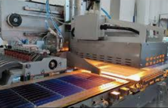
If your heat is uneven, your circuit boards are in trouble. It’s that simple. To stop boards from warping or solder joints from cracking, we pair digital temperature controllers with shortwave IR emitters. It’s the best way to keep the thermal profile locked in during reflow and curing.
How we handle the heat
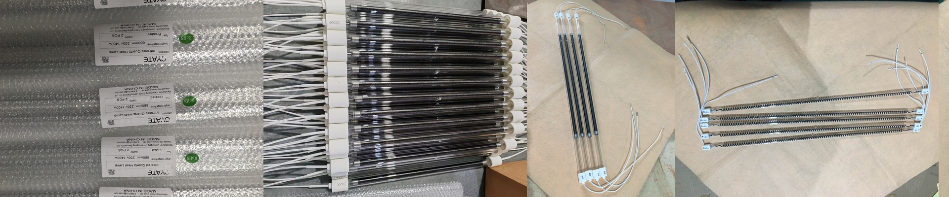
We don’t just blast the board with heat; we target it. By tweaking the wattage and voltage on the IR lamps, you control exactly how much energy hits the surface. If you’re running a high-volume line, you need speed. High-wattage tubes get you up to temp fast. The magic here is that you get a concentrated heat zone that sinks deep into the board without frying the delicate surface-mount components on top.
The nitty-gritty on the gear
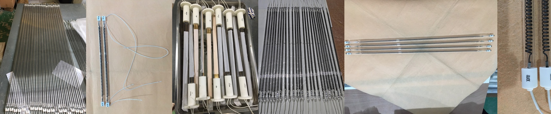
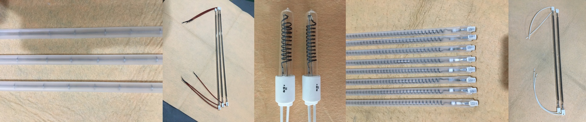
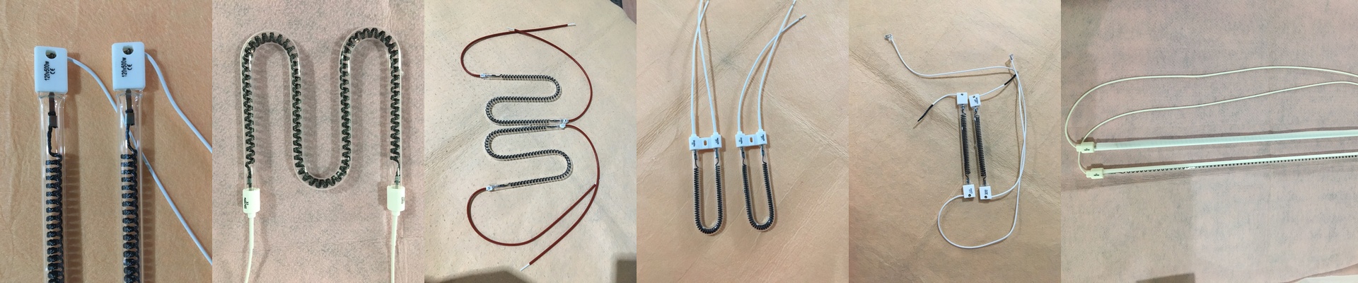
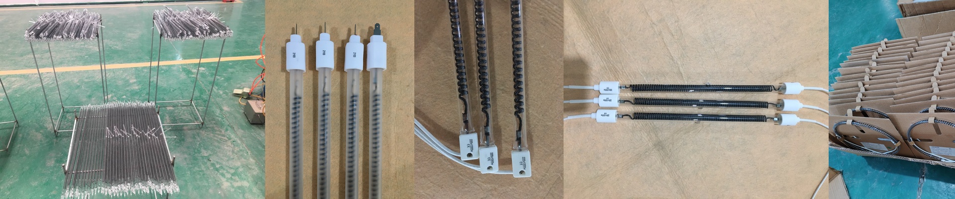
We use tungsten filaments tucked inside quartz glass. Why quartz? Because it doesn’t crack when things get hot and cold quickly, unlike standard glass. We also kept the connectors standard. That means these units are basically drop-in replacements. You can wire them up and get back to work without having to build custom brackets or fabricate new parts. Plus, we often coat the tubes. This shifts the emission spectrum so the solder paste actually absorbs the heat instead of the board substrate just bouncing it away.
The trade-offs (The part people forget)
Here’s the thing: high heat density isn’t free. When you push these lamps to the limit to speed up production, they throw off a massive amount of ambient heat. If your exhaust hoods and fans aren’t up to the task, your controller will hit a thermal cutout to save the circuitry. And that’s a nightmare for your uptime. The secret is all in the spacing. Finding that sweet spot between the lamp and the board is the only way to keep your throughput high without risking your components.